 |
800.514.3066customer service |
|||||||||||||||||||||||||||||||||||||||||||||||||||||||||||||||||||||||||||||||||||||||||||||||||||||||||||||||||||||||||||||||||||||||||||||||||||||||||||||||||||||||||||||||||||||||||||||||||||||||||||||||||||||||||||||||||||||||||||||||||||||||||||||||||||||||||||||||||||||||||||
|
|
Kaydon white papersShifting gears: simplify your design with slewing ring bearingsA slewing ring bearing has rolling elements designed to create a reactive moment within the bearing's dimensions envelope, to oppose applied (overturning) moment load. This makes it practical to use one bearing instead of two, reducing the height required for an application and often improving performance. In addition to saving space, a designer can use a slewing ring bearing to simplify a drive system by incorporating gear teeth on the inner or outer race. These gear details can take on many styles and features: Fellows stubs, full-depth involutes, straight or helical, hardened or unhardened, ground or unground. Whatever its style, the success of a slewing ring gear depends on four factors: gear static strength, resistance to pitting, gear fatigue, and gear/pinion interfaces (or mesh). 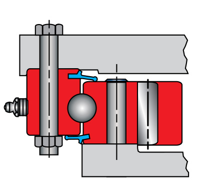
Stationary inner race 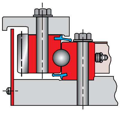
Rotating outer race 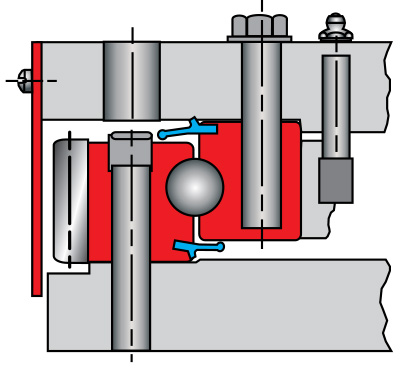
Stationary outer race 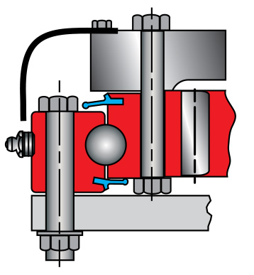
Rotating inner race A pressure angle of 20° is most common because 20° cutters are standard, but 14.5°, 25°, or special pressure angles may also be used. Machine designers generally select slewing ring bearings based on load capacities (see Figure 2). The tooth size and form is then selected using the following Lewis equation:
L = SFY P (where L = Tangential tooth load)  
A stub tooth form is often used in large gears, primarily for economy. The form requires less material in the ring forging than full depth tooth forms, and less gear cutting time. Full depth tooth forms provide a greater contact ratio for smoother operation, but they also have lower bending strength. With core hardness of 23 to 30 Rc, allowable bending stress is 34,000 psi. With 262 to 302 BHN (27 to 32 Rc) it is 37,000 psi, and 29 to 34 Rc allows 40,000 psi. These stress approximations are for maximum or stall torque conditions...when shock is included in the loading, stresses may be higher. When high tooth surface pressures are constant, induction-hardened gear teeth with a minimum surface hardness of 55 Rc should be considered. An example of this would be an excavator or logger that undergoes high acceleration rates and rapid deceleration during a swing cycle. A full root radius with root hardening (see Figure 4) is also recommended; the tooth pattern and depth of hardness are critical here.
BacklashAll gears need backlash room. This is especially true of bearing gears, which have large diameters and large center distances that demand greater manufacturing tolerances. Adjusting the center distance between gear and pinion is one way to gain backlash room. This allows a greater gear size tolerance (and extended life) with take-up for wear, which can save money in the long run.
InstallationInstallation of bearing/gear assemblies should be done in a clean, dry, well-lit area. Housing mounting surfaces and pilots should be unpainted and wiped clean of chips, dirt, and lint, because even soft materials make high spots when entrapped. Any weld spatter, nicks, and burrs should be removed. The bearing can be lifted or hoisted into position using eye bolts in mounting holes (or nonmetallic slings) to prevent damage to bearing surfaces and gear teeth. Inherent to the hardening process of most turntable bearings is a small gap at one point in the raceway, where loading holes are drilled. These gaps (and load hole plugs, in races with through holes) should be positioned at minimum load points, if possible. Load hole plugs in races with tapped holes or weld rings must be so positioned. With the rotating race, this is done by placing the loading hole 90° off the maximum load zone from moment loading. With the stationary race, this position depends upon the location of the lightest load relative to the lower structure of the machine. 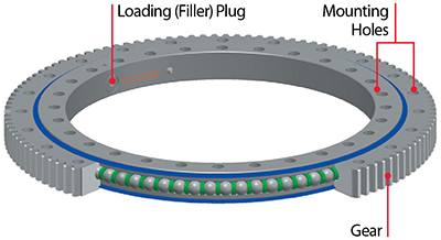
For good internal load distribution and smooth, low-torque operation, the bearing should be as round as possible when the bolts are tightened. If one race is doweled or piloted, it should be mounted first whenever possible. On unpiloted gear bearings, the gear/pinion backlash should be checked and adjusted. The minimum backlash point of the gear is often identified by yellow paint in the tooth space.
There are several things to keep in mind when installing a bearing/gear assembly:
After these steps have been taken, check gears on fixed centers for backlash and then set pinions on adjustable centers for the proper backlash. When all backlash checks are complete, the gear should be coated with grease suitable for the operating conditions and rotated to ensure coverage of all contacting surfaces with the pinions. Finally, complete the installation of all rotating components of significant weight, and check the bearing for freedom of rotation. Again, excessive torque or variations may indicate an unsatisfactory installation condition. SummaryGeared slewing ring bearings are a great solution for simplifying drive systems, especially when space is limited. Designers should carefully consider static strength, fatigue, resistance to pitting, and gear/pinion interfaces when choosing a bearing for any application, and should include backlash room in their designs. As the world's foremost producer of slewing ring bearings, Kaydon Bearings is especially qualified to help designers use them to solve application problems. If you have such a problem, our highly experienced application engineering staff would welcome your call. Download this article
Shifting gears: simplify your design with slewing ring bearings |
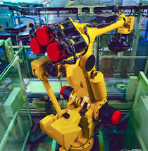
Slewing ring bearings are surprisingly versatile Slewing ring bearings have traditionally been thought of as large-diameter, heavy-section, low-precision bearings, and bore sizes of over 800 mm are still very common. But today they are also available with bore sizes as small as 50 mm, making them ideal for robotics, radar pedestals and other precision applications. Small, off-the-shelf slewing ring bearings (preloaded to eliminate clearance and improve stiffness) are now standard in machine tools, with runout and diameter tolerances specified in ten-thousandths of an inch vs. thousandths. Selecting the right slewing ring bearing depends on design requirements for load, stiffness, speed, size, and smoothness of rotation. Traditional king-post bearing mounting arrangements (to support radial, thrust, and moment loads) have two ball or roller bearings spaced along a common axis. Their moment capacity is boosted by spacing the bearings further apart and using heavier sections, which can complicate mounting and limit their suitability for many new applications. A better solution these days is a single four-point contact ball bearing. This type utilizes gothic arch construction for the inner and outer race ball paths, generating four points of contact for each ball. This design generates intersecting contact angles that create a large effective pitch diameter to offset any overturning moment load. The use of a single large-diameter bearing makes it possible for wiring and plumbing to run through the bore of the bearing. This can simplify overall design, help protect components, and improve appearance. Although bearing cross-section and diameter selection are dominated by load vs. capacity considerations, other parameters can be important. Torque considerations, for example, may indicate the use of a two-row ball bearing in place of a four-point contact bearing. Increased moment stiffness may require a two-row roller or a cross-roller bearing. Deflections, or the use of an aluminum mounting structure, may dictate the need for an aluminum wire race version of a steel ball or roller bearing. Aluminum bearing rings with hardened steel wires can not only match the coefficient of expansion of aluminum mounting structures, but can also provide the flexibility needed to compensate for mounting distortions. |
||||||||||||||||||||||||||||||||||||||||||||||||||||||||||||||||||||||||||||||||||||||||||||||||||||||||||||||||||||||||||||||||||||||||||||||||||||||||||||||||||||||||||||||||||||||||||||||||||||||||||||||||||||||||||||||||||||||||||||||||||||||||||||||||||||||||||||||||||||||||||
|
||||||||
|
|
||||||||