spacer spacer spacer spacer
Kaydon Bearings spacer spacer

Contact Us


spacer
spacer

Kaydon slewing bearings

KH series

Kaydon's KH series precision slewing ring bearings are designed to provide precise positioning with consistent repeatability, in applications where rotation is constant, intermittent or oscillating. KH slewing rings offer a wide variety of solutions for advanced rotary index tables or any design where the bearing will mesh with other precision mechanical components.
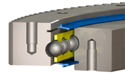
 

spacer

 
Log in to access Slewing Bearing 3D models & CAD files. Access Thin Section Bearings at SKF.com
 
Forgot password?  |  Register

spacer

Specifications

 
No gear
External gear
Dynamic & intermittent capacities
Notes & related items


spacer
spacer
Kaydon Bearings - KH turntable 3D

Design features
The internal configuration is a deep groove gothic arch raceway, which provides four points of contact with the balls, enabling it to carry radial, moment, and thrust loads individually or simultaneously. The use of internal diametral preload provides for greater stiffness, which combined with tightly controlled radial and axial runouts, delivers accurate repeatability. The axial runouts are 0.001 inches TIR and the radial runouts for locating diameters are 0.002 inches TIR. A separator is used to maintain consistent ball spacing interval, keep friction to a minimum, and minimize noise. Integral face riding seals are provided to assist in the exclusion of contaminants.

KH series precision bearings are offered in nongeared and externally geared configurations. The gears have full depth involute teeth and are manufactured to an AGMA Class Q8 quality, allowing for decreased backlash, more accurate positioning, and less noise while operating.

Availability
KH series slewing bearings have a rectangular cross-section, range in size from 16–37 inches OD (400–950 mm), and are generally available from stock.

Applications
KH series slewing ring bearings have been used successfully in applications demanding higher precision, including:

  • Precision rotary index tables
  • Radar antennas
  • Satellite antennas
  • Robots
  • Medical systems and medical devices
  • Machine tool tables
  • Any design where the KH bearing will interface with other precision components

Click on the Kaydon part number to view and download 3D models and CAD files. You must login or register before accessing drawings.

spacer

See glossary of symbols

Kaydon Bearings - KH series turntable profile - no gear
No gear
Kaydon
part
number
Load
chart
Outline dimensions & weight Mounting holes Gear data Max
gear tooth
load
Fz
(lbs)
Do
(in)
di
(in)
Di
(in)
do
(in)
G
approx.
(lbs)
Outer ring Inner ring
Lo
(in)
no Li
(in)
ni D2
(in)
b2
(in)
Z2
KH-125P load chart 16.500 8.625 12.750 12.250 80 14.750 16 10.250 16 - - - -
KH-166P load chart 20.500 12.750 16.875 16.375 105 18.875 20 14.375 20 - - - -
KH-225P load chart 26.700 18.500 22.750 22.250 150 24.500 18 20.500 18 - - - -
KH-275P load chart 31.700 23.500 27.750 27.250 185 29.500 24 25.500 24 - - - -
KH-325P load chart 36.700 28.500 32.750 32.250 220 34.500 28 30.500 28 - - - -
Tolerances ±.050 ±.050 * *   .030   .030          

See glossary of symbols

Kaydon Bearings - KH series turntable profile - external gear
External gear
Kaydon
Bearings
part
number
Load
chart
Outline dimensions & weight Mounting holes Gear data - FD involute
Pd = 6, α = 20°, AGMA Q8
Max
gear tooth
load
Fz
(lbs)
Do
(in)
di
(in)
Di
(in)
do
(in)
G
approx.
(lbs)
Outer ring Inner ring
Lo
(in)
no Li
(in)
ni D2
(in)
b2
(in)
Z2
KH-125E load chart 16.500 8.625 12.750 12.250 75 14.750 16 10.250 16 16.167 2.000 97 5,480
KH-166E load chart 20.500 12.750 16.875 16.375 100 18.875 20 14.375 20 20.167 2.000 121 5,570
KH-225E load chart 26.667 18.500 22.750 22.250 140 24.500 18 20.500 18 26.333 2.000 158 5,670
KH-275E load chart 31.667 23.500 27.750 27.250 175 29.500 24 25.500 24 31.333 2.000 188 5,700
KH-325E load chart 36.667 28.500 32.750 32.250 205 34.500 28 30.500 28 36.333 2.000 218 5,730
Tolerances   +0/-.020 ±.050 * *   .030   .030     ±030    

See glossary of symbols

 
Dynamic & intermittent capacities
Size Dynamic Intermittent
Axial
(lbs)
Moment
(ft-lbs)
Axial
(lbs)
Moment
(ft-lbs)
KH-125 32,000 13,100 60,000 25,800
KH-166 36,000 20,500 82,800 45,200
KH-225 40,000 30,500 115,200 56,000
KH-275 43,000 39,600 142,000 75,000
KH-325 45,000 48,100 167,000 92,000

spacer
 
warning sign

spacer
Notes
Damage to equipment and danger to human life can result from failure to heed the recommendations in the text identified by the warning symbol in Kaydon Catalog 390 where further details and additional considerations can be found.

Dynamic-L10 capabilities based on million revolutions. Values do not apply simultaneously. Intermittent-Individual capacity limits for maximum loading when normal mode of operation is an intermittent load application and rotation.

* Di = do = +0/-.002 tolerance for KH-125 through KH-225
* Di = do = +0/-.003 tolerance for KH-275 through KH-325

Related pages
Slewing ring bearing selector
Turntable glossary of symbols

Related downloads
Catalog 390: KH series (Adobe PDF)
Catalog 390: all pages (Adobe PDF)

Adobe Acrobat Reader

spacer spacer